
By AGILE Consulting Engineers, Solar PV and Battery Energy Storage Systems (BESS) specialists.
Scale changes the engineering problem, not just the size of it. A rooftop system and a hundred-megawatt ground-mount plant are not the same design exercise done at different volumes. Utility-scale ground-mount solar, increasingly paired with Battery Energy Storage System (BESS) capacity on the same site, introduces layout, electrical and grid-interface decisions that simply do not arise, or do not matter as much, at smaller scale.
Table of Contents
- What “Utility-Scale” Changes About the Design Task
- Array Layout Optimisation
- DC to AC Ratio and Inverter Loading Decisions
- Inverter and Transformer Siting
- Substation and Grid Interface Design
- Connection Study Coordination
- BESS Integration at Utility Scale
- What to Do Next
- FAQ
What “Utility-Scale” Changes About the Design Task
At utility scale, decisions that are minor at a small commercial installation become significant capital and performance levers. A marginally inefficient array layout across a few hundred kilowatts is a rounding error. Across a hundred megawatts spread over several hundred hectares, the same inefficiency compounds into a meaningful loss of annual generation and a real difference in project economics. Utility-scale projects also engage directly with the formal grid connection framework administered through the National Electricity Market (NEM, Australia’s wholesale electricity market covering the eastern and southern states) rather than the simplified connection pathways available to smaller systems, which brings its own design obligations. Detailed design at this scale is as much about optimisation and coordination across a large, variable site as it is about correctly specifying individual components.
Array Layout Optimisation
Array layout at utility scale is a genuine optimisation problem, not a repeating pattern stamped across a site boundary. Row spacing has to balance land use against inter-row shading losses, which depend on latitude, tilt angle and the site’s specific terrain. Orientation and tracker or fixed-tilt selection interact with local wind loading and the structural standard the design needs to satisfy. Access roads, drainage corridors, easements and any environmentally sensitive areas identified during approvals all constrain where arrays can physically sit, and those constraints rarely align neatly with an idealised rectangular layout.
Topography adds another layer. Sites with meaningful grade change need the layout worked against a topographic survey early, since cut and fill decisions affect both civil cost and how consistently rows perform relative to each other. Getting the layout right is a matter of working these constraints together rather than optimising any single one in isolation, which is why it is normally done iteratively against a coordinated site model rather than as a single upfront exercise.
DC to AC Ratio and Inverter Loading Decisions
The relationship between a plant’s DC array capacity and its AC inverter capacity, commonly expressed as the inverter loading ratio, is one of the more consequential decisions in utility-scale design because it interacts directly with capital cost, clipping losses and inverter utilisation. Industry data shows the average DC to AC ratio for utility-scale PV has trended upward over the past decade, with individual system ratios commonly in the 1.13 to 1.3 range and some modern designs pushing higher, reflecting the falling relative cost of modules against inverters and a design philosophy oriented toward maximising annual energy rather than peak output alone.
The right ratio for a given project depends on site-specific factors: ambient temperature profile, since cooler and clearer climates raise DC output and clipping risk, module thermal behaviour, inverter thermal derating headroom at high ambient temperature, and how the offtake arrangement or market participation strategy values shoulder-season and winter generation against midday clipping. This is a modelling exercise specific to the site and equipment selected, not a figure that transfers reliably from one project to another.
Inverter and Transformer Siting
Where inverters and transformers physically sit within the array has direct consequences for cable losses, voltage drop and capital cost, since DC and AC cable runs scale with distance from generation to conversion equipment. At utility scale, the design typically works toward siting inverter stations and associated transformers to minimise aggregate cable length across the array while keeping equipment accessible for maintenance and away from drainage lines, flood-prone areas and any site constraints identified during civil and geotechnical assessment.
This siting decision also has to account for how power is collected and aggregated before reaching the main substation, since the medium-voltage collector network design and the number and placement of inverter stations are interdependent decisions rather than ones that can be made sequentially without revisiting earlier choices.
Substation and Grid Interface Design
At the point where the plant meets the wider network, the design has to address, at a conceptual level, how power is stepped up from the collector voltage to the connection voltage, what switchgear and protection are required at the interface, and how the substation is configured to meet the network operator’s technical requirements. This is genuinely joint work between the plant’s electrical design and the requirements set by the Distribution Network Service Provider (DNSP, the entity that owns and operates the local distribution network) or, for larger transmission-connected projects, the relevant transmission network service provider.
The substation design also needs to anticipate the protection and control philosophy for the whole plant, since fault levels, protection coordination and metering arrangements at this interface are shaped as much by the network operator’s standards as by the plant’s own configuration.
Connection Study Coordination
Utility-scale projects in the NEM go through a formal connection process administered through AEMO’s (Australian Energy Market Operator, the body that operates the National Electricity Market) Generator Performance Standards framework, which sets minimum and automatic technical access standards, with a negotiated tier in between for requirements that sit outside the automatic standard. As of August 2025, amendments to the connection standards for generators and BESS came into effect, intended to better accommodate inverter-based generation such as solar PV and utility-scale BESS and to streamline the connection process, including changes to frequency response requirements for both technologies.
Detailed design has to be coordinated closely with this process, because the connection study can influence equipment specification, protection settings and even aspects of the electrical layout. A design finalised in isolation from the connection study risks needing rework once study outcomes are known, which is why connection study coordination is treated as a parallel, ongoing input to detailed design rather than a box ticked at the end.
BESS Integration at Utility Scale
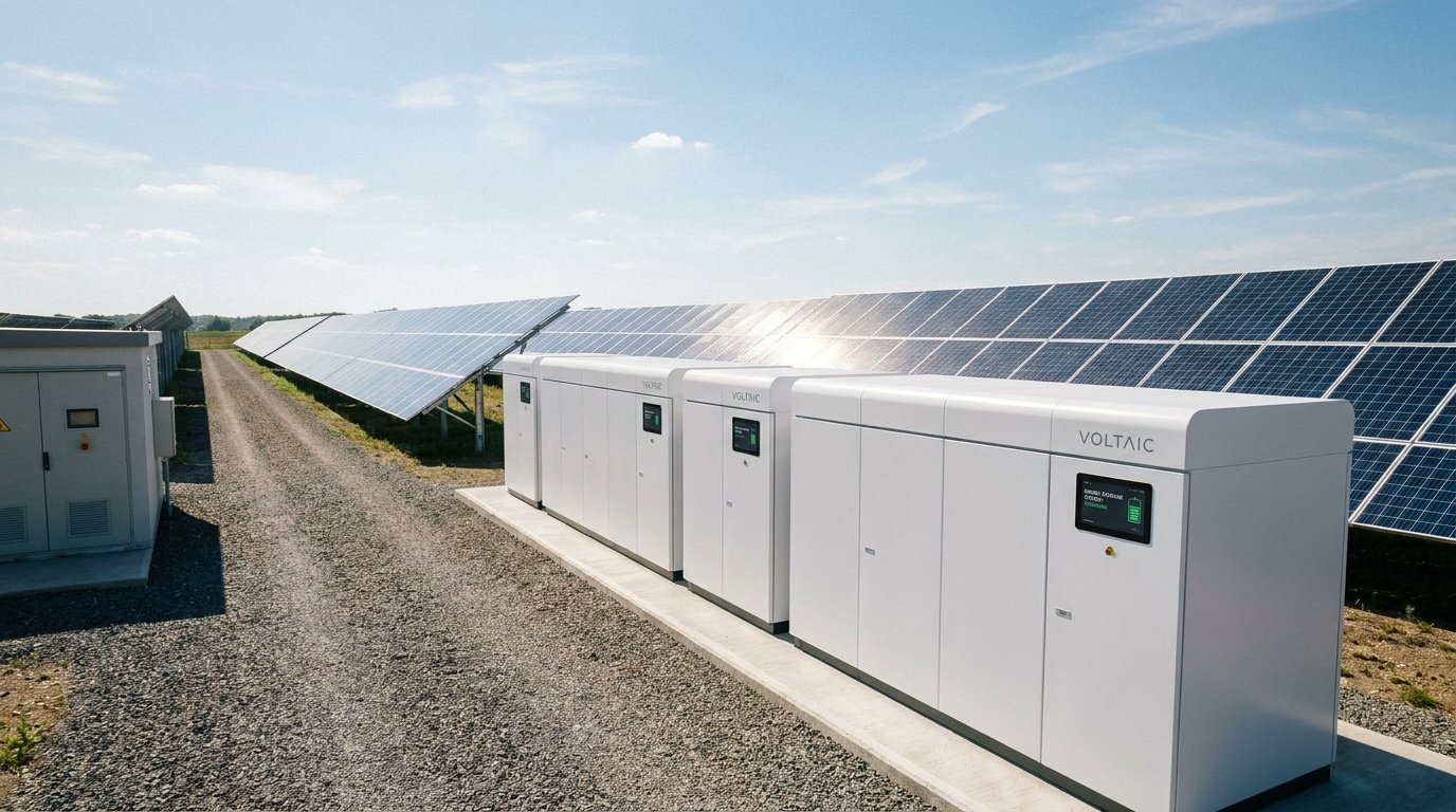
Where a utility-scale project includes BESS alongside solar generation, the detailed design has to treat the two as an integrated system rather than two projects sharing a fence line. The DC to AC ratio of the solar array affects how and when the battery can charge from generation. The power conversion system topology chosen for the battery affects the plant’s overall connection study and how it presents to the grid. The energy management system logic governing how the combined asset dispatches, charges and discharges determines whether the plant actually captures the revenue streams, including frequency response participation, that its design was intended to enable. Coordinating these decisions across the solar and storage components, rather than optimising each independently, is one of the defining characteristics of detailed design for a hybrid utility-scale asset.
What to Do Next
Utility-scale ground-mount design carries a lot of interdependent decisions, layout, DC to AC ratio, siting, substation configuration and connection study coordination, that are genuinely easier to get right when they are worked through together rather than sequentially by separate teams. AGILE’s solar and BESS system design service is built around coordinating exactly this scope for utility-scale projects moving toward construction readiness.
FAQ
What size project is generally considered utility-scale in Australia?
There is no single fixed threshold, but the term generally applies to projects large enough to require formal transmission or distribution-level connection and AEMO’s Generator Performance Standards process, typically from several megawatts upward, with the design considerations described here becoming increasingly significant as scale increases.
How does terrain affect array layout at utility scale?
Sites with meaningful grade change require the layout to be worked against topographic survey data early, since row spacing, inter-row shading and civil cut and fill costs are all sensitive to terrain in ways that flatter sites are not.
Is a higher DC to AC ratio always the more efficient design choice?
Not universally. It depends on the site’s climate, selected equipment and how the project values shoulder-season output against midday clipping losses, so the ratio needs to be modelled for the specific project rather than defaulted from a rule of thumb.
What changed in AEMO’s connection standards in 2025?
As of August 2025, amendments took effect intended to better accommodate inverter-based generation such as solar and BESS and to streamline the connection process, including changes to how frequency response requirements are defined for both technologies.
Why does BESS need to be designed together with the solar array rather than separately?
Because the solar array’s DC to AC ratio, the battery’s power conversion system and the site’s energy management logic all interact, and optimising each component independently risks leaving performance or revenue on the table compared with a coordinated design.
How early should connection study engagement start relative to detailed design?
As early as practical, since connection study outcomes can influence equipment specification, protection settings and layout decisions, and finalising detailed design in isolation from this process risks rework once study results are available.
