
A solar farm and a battery storage system are each complex engineering assets in their own right. When you co-locate them as a hybrid project, the design interdependencies multiply. The DC/AC ratio of the solar array affects the BESS charging profile. The Power Conversion System (PCS) topology affects the grid connection studies. The Energy Management System (EMS) logic determines whether the combined system actually captures the revenue it was modelled to generate.
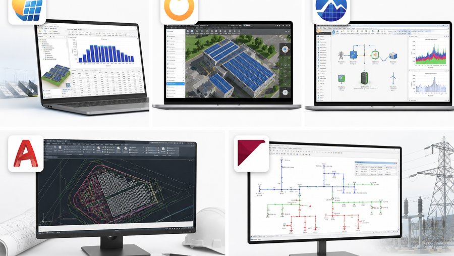
AGILE Consulting Engineers provides detailed system design review and independent technical advisory for solar BESS hybrid projects across Australia. We use HelioScope, PVSyst, and Homer Pro to model system performance, and we bring the grid integration context that pure energy yield software does not provide.
Solar PV design centres on energy yield. You are optimising array layout, tilt, azimuth, inverter configuration, DC/AC ratio, and cable routing to maximise annual generation while managing clipping losses and staying within grid export limits.
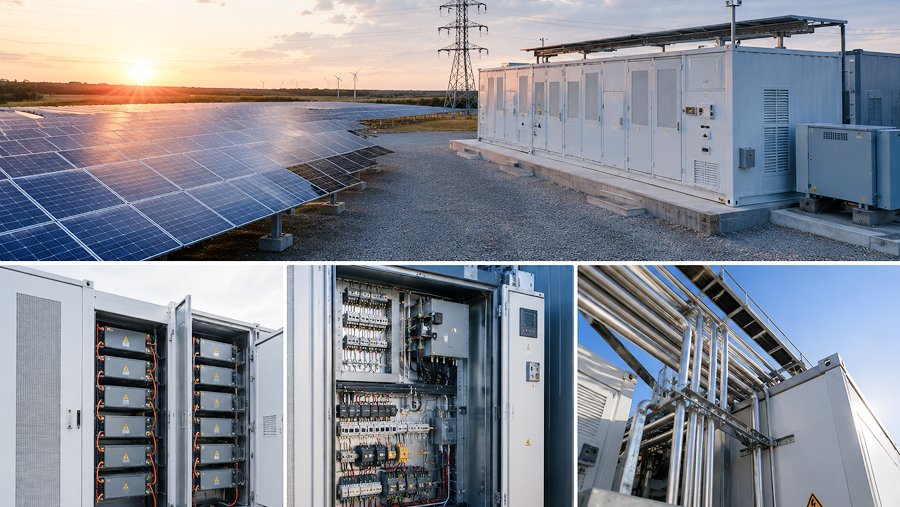
Battery Energy Storage System (BESS) design centres on power and energy sizing, duration, round-trip efficiency, thermal management, degradation curves, and the revenue logic of the EMS. A BESS sized for Frequency Control Ancillary Services (FCAS) participation requires a different specification than one sized for firming a solar farm’s export profile.
When the two assets share a grid connection point, every design decision in one affects the other. The solar clipping profile affects BESS charging opportunity. The grid connection agreement’s reactive power requirements affect both solar inverter specifications and the PCS configuration. The protection coordination at the shared MV bus affects both assets’ fault ride-through performance.
Getting the interface between these two design domains right is where hybrid projects most commonly run into problems during commissioning.
We conduct energy yield modelling using PVSyst and HelioScope, covering array configuration, inverter selection, DC/AC ratio analysis, soiling and degradation assumptions, and shading analysis. We review Performance Ratio (PR) targets against site-specific conditions and check that yield model assumptions are defensible for financial modelling and lender due diligence.
We also review the reactive power capability requirements specified in the grid connection agreement and confirm that the selected inverter can meet voltage control obligations under the relevant network technical requirements.

Using Homer Pro and financial modelling frameworks, we assess the optimal BESS sizing for the project’s intended use cases. Power capacity in MW, energy capacity in MWh, duration in hours, and round-trip efficiency all interact with the revenue model. A BESS sized purely for FCAS will have a different energy-to-power ratio than one designed to firm a solar export profile for a Power Purchase Agreement (PPA).
We review battery chemistry options, AC-coupled versus DC-coupled topology, container configuration, thermal management approach, and augmentation provisions for capacity degradation over the asset life. We do not represent any battery OEM, which means our technology recommendations are based on project requirements, not commercial relationships.
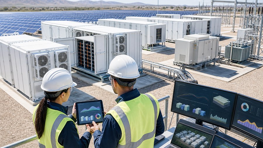
Solar BESS projects connecting to the National Electricity Market (NEM) require grid connection studies that assess the combined plant’s impact on the network. Connection studies typically cover steady-state load flow and voltage analysis, fault level contribution, harmonic emissions assessment, and dynamic modelling for fault ride-through and generator performance standard compliance.
We work with developers to prepare the technical information required for connection applications, review network service provider technical queries, and assess the implications of connection conditions on the system design.

The shared MV bus of a co-located solar BESS project is a protection engineering challenge. The fault current contribution from the BESS PCS must be accounted for in the protection grading study. We review single line diagrams, protection philosophies, and relay settings for consistency with both the network’s requirements and the equipment’s actual fault current characteristics.

The Energy Management System (EMS) governs how the solar and BESS assets interact in real time. We review the EMS control architecture against the project’s revenue objectives and grid connection obligations, checking that dispatch logic, state of charge management, and grid support functions are correctly specified.

If your solar BESS project is in early design and you are not sure whether your DC/AC ratio assumptions, BESS sizing logic, or EMS specification are internally consistent, a design review at that stage is the most efficient use of engineering budget. We have helped teams identify significant design issues before they became construction problems.
There is no universal answer. The optimal DC/AC ratio depends on the grid connection export limit, local irradiance profile, BESS charging strategy, and the revenue model. A higher DC/AC ratio increases clipping losses but can also increase BESS charging opportunity during peak generation periods. The right answer comes from modelling the specific project, not from applying a rule of thumb.
Both topologies have legitimate applications. AC-coupled systems use separate PCS units for the solar and BESS, which gives operational flexibility and simplifies protection design. DC-coupled systems share the inverter between solar and BESS, which can improve round-trip efficiency but creates more complex interface design requirements. The choice depends on the project’s dispatch strategy, connection voltage, and equipment availability.
Battery cells lose capacity over time due to cycling and calendar ageing. A BESS delivering 100 MWh at commissioning may deliver significantly less after ten years of operation. Good design accounts for this through initial oversizing, an augmentation provision in the equipment contract, or both. Modelling degradation accurately is important for financial model integrity and for warranty negotiations with the OEM.
Connection requirements depend on the project size and the connecting network. For NEM-connected projects, AEMO’s Generator Performance Standards and the relevant network’s technical requirements govern the studies needed. Typical studies include load flow analysis, fault level assessment, harmonic compliance, and dynamic modelling for fault ride-through. We support developers in preparing the technical package for connection applications.
Yes. Homer Pro is particularly well suited to off-grid and remote area power system design, where the optimisation objective is diesel displacement, reliability of supply, and lifecycle cost rather than NEM market participation. We have experience with remote community power systems and Pacific island applications.
Contact AGILE Consulting Engineers to discuss your solar BESS design review requirements. We will give you a clear picture of what independent technical review adds to your project at each stage.